I Built My Own Sega Genesis Controller
The most comfortable controller ever constructed.
 Toolbox Toolbox |
June 3, 2024 |
Yup. I built my own Sega Genesis controller. It even works! In this post I'm going to explain why I built it and how I did it.
I've recently had this crackpot idea to build an arcade cabinet based on a Sega Genesis. I had this idea while I was playing Streets of Rage 2 with my Genesis Arcade Power Stick. That game feels so good to play with the arcade stick, so I thought "wouldn't it be awesome to play this game with actual arcade hardware?"
I have a spare Sega Genesis laying around that I got up and running, so I could use it as the core of my cabinet. I can plug speakers into the stereo headphone jack (with built-in volume control), and it's likely possible to have some kind of cartridge-selection system like in Nintendo's old playchoice 10 machine. I could also set up some kind of coin-fed timer that provides an operator-set amount of playtime, resetting the console once the timer is up.
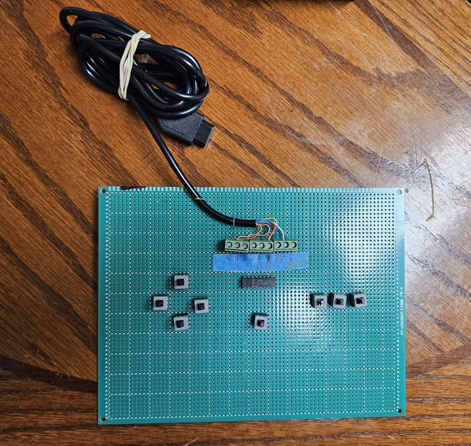
Ambitious for sure, especially since I have no experience whatsoever restoring or building arcade cabinets. So, I figured I'd start out small by building my own arcade stick with sanwa buttons and a nice clicky joystick. Of course, I don't have arcade input components, so I ripped the cables off of some PC motherboard reset switches instead. It's definitely not comfortable, but it's a functional prototype. Oh yeah, I lied about this controller being comfortable.
Also, I'm not the first person to come up with this idea. This YouTube video by RetroBuiltGames in particular is a prime example of this idea put into practice. After I had the idea I looked it up to see if someone had already done it, and sure enough this guy did an amazing job with it. I can only dream that my cabinet is anywhere near as good as his. His videos for his project are major inspirations and motivations for my own project. He also built his own arcade stick!
I easily could have just soldered some buttons to an existing Genesis controller, but where's the fun in that? Also, I don't want to sacrifice or harvest parts from existing OEM controllers if I can avoid it, especially if it's in working order. So, I reversed engineered Sega's controller and ordered the parts that I didn't have online.
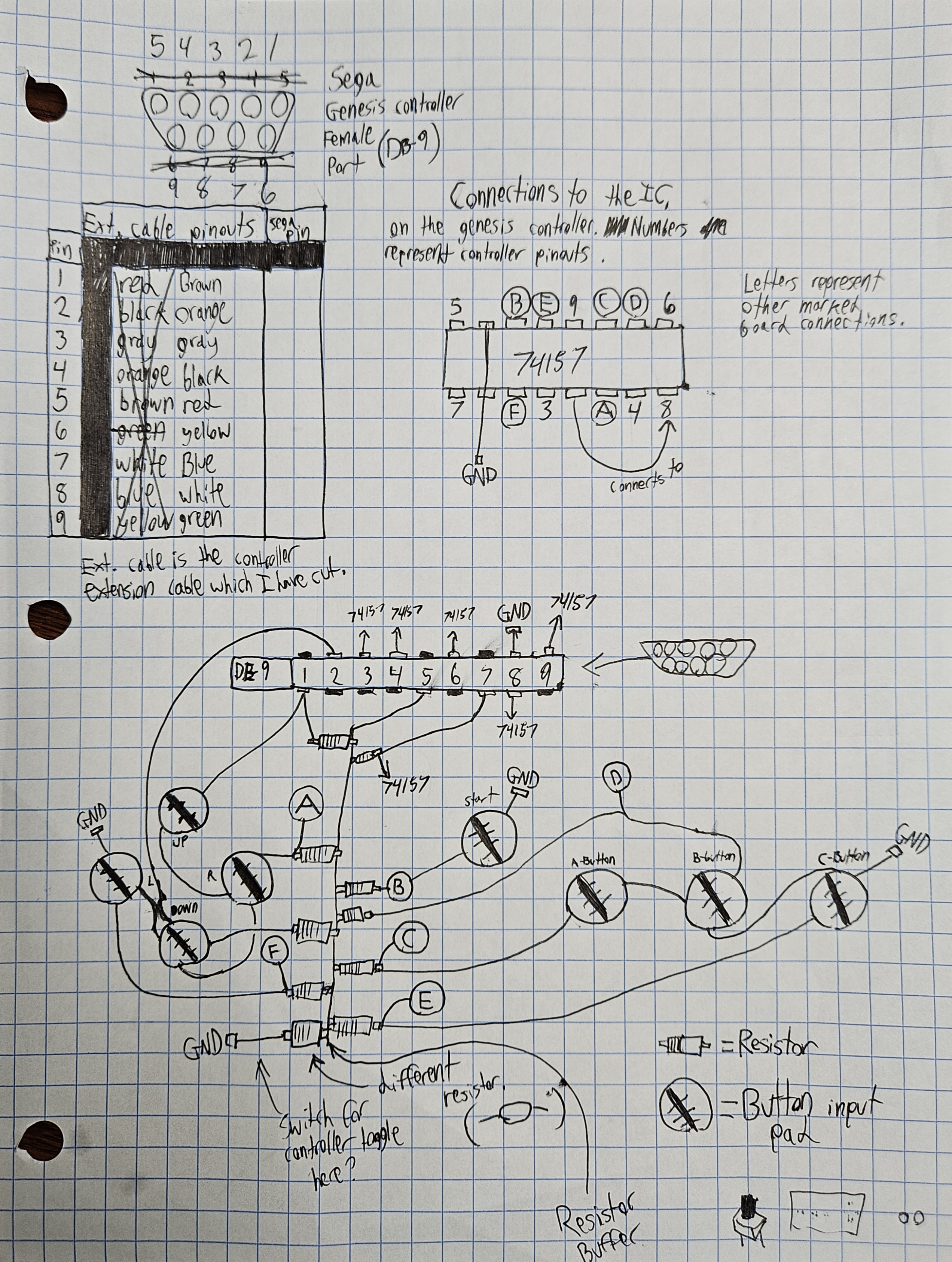
Even though there are schematics and diagrams out there of the 3-button controller, I can't read schematics for shit. For whatever reason it made more sense to me when I mapped it out myself on paper in my own mad-scientist scribblings, as weird and stupid as that sounds.
I essentially just followed the traces and slowly mapped out how the components of the controller are connected on paper, like some sort of circuit cartographer.
Also, a word of advice if you plan to do this: remove the chip on the OEM controller before probing the cable pinouts with a multimeter. If you leave the chip installed, one pinout might have continuity with multiple cables, as most of them connect to the chip at some point.
I want to point out that the view of the 74157 chip in my notes is looking from above with the text on the chip being readable (not upside down or anything).
By the way, here's a list of parts that I used for this project:
- (x1) aftermarket 6ft Genesis controller extension cable
- (x1) protoboard
- (x8) 10k resistors
- (x1) 74157 multiplexer chip
- (x3) 3-hole screw-down wire terminals
- (x8) buttons (I used reset buttons meant for a PC motherboard)
- some wires that I had laying around
- some regular old staples
I originally wanted to make a 6-button controller, but the chip used in that controller is one that was specially designed by Sega. As far as I can tell there is no alternative to that chip (I hope I'm wrong about that). Also, I don't have enough buttons laying around for that.
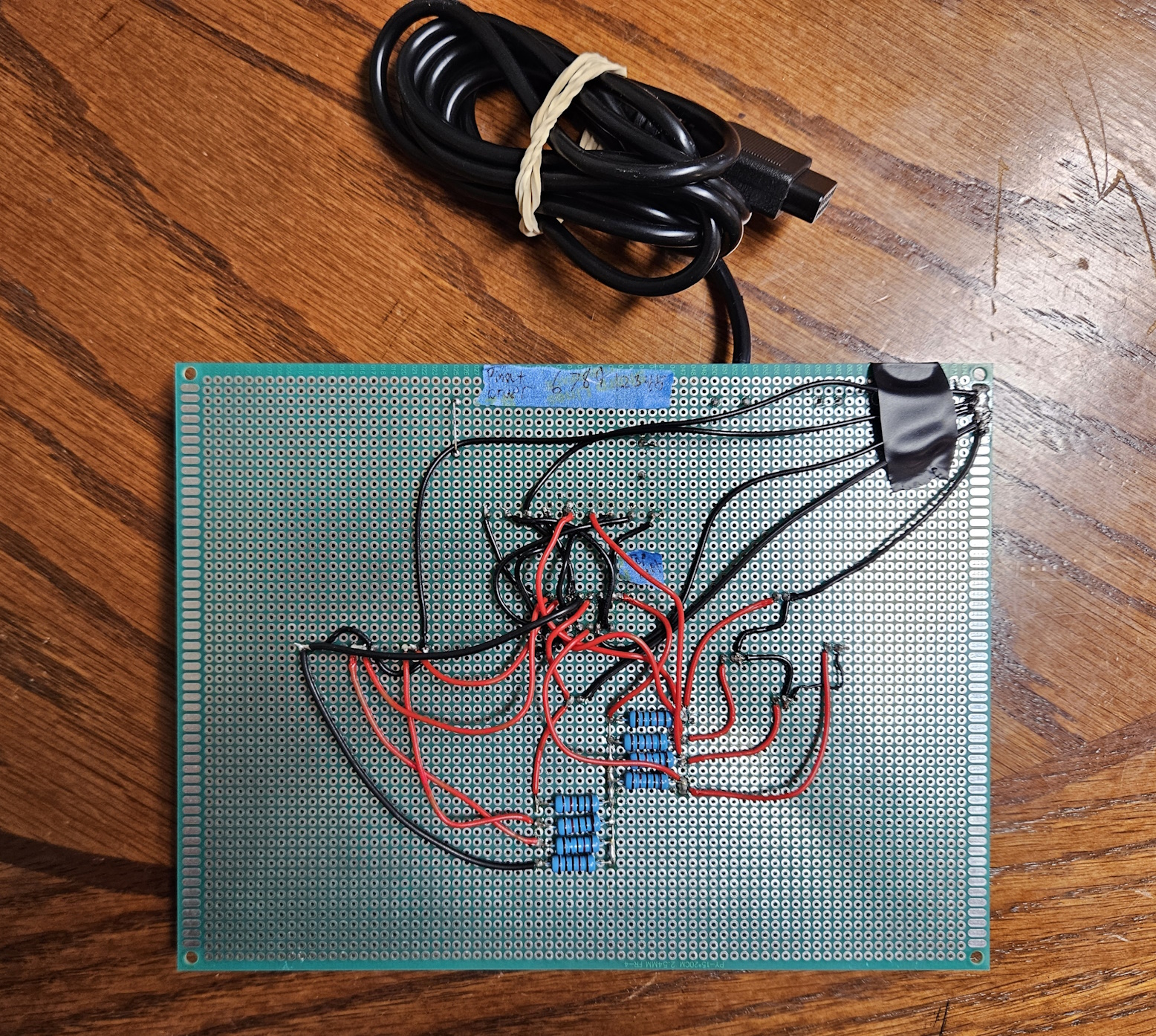
Here is the wire-spaghetti on the underside of the protoboard. It's not pretty, but it gets the job done. Honestly, my board layout makes little sense, and definitely could have been planned better. After I mapped out the circuitry I kinda just winged how it would all be routed in practice. It was definitely a learning process. I found that it was tricky to solder the wires that all converge on the 74157 chip. The more wires I added, the harder it was not to melt the surrounding cables as I soldered wires in between, under, or over other wires. Towards the end I was starting to think that it would have just been easier to learn CAD, design my own PCB, then order my design online.
For each wire I grabbed my entire length of wire, held the end of the wire on the component then fed out however much length was need to connect it to the chip or whatever I was connecting it to. Then, I would cut that length (with some slack), strip both ends of the wire, "tin" the ends of the wire (twisting the tips and adding solder to it), then finally attach the wire accordingly with my soldering iron. I repeated this process for every wire.
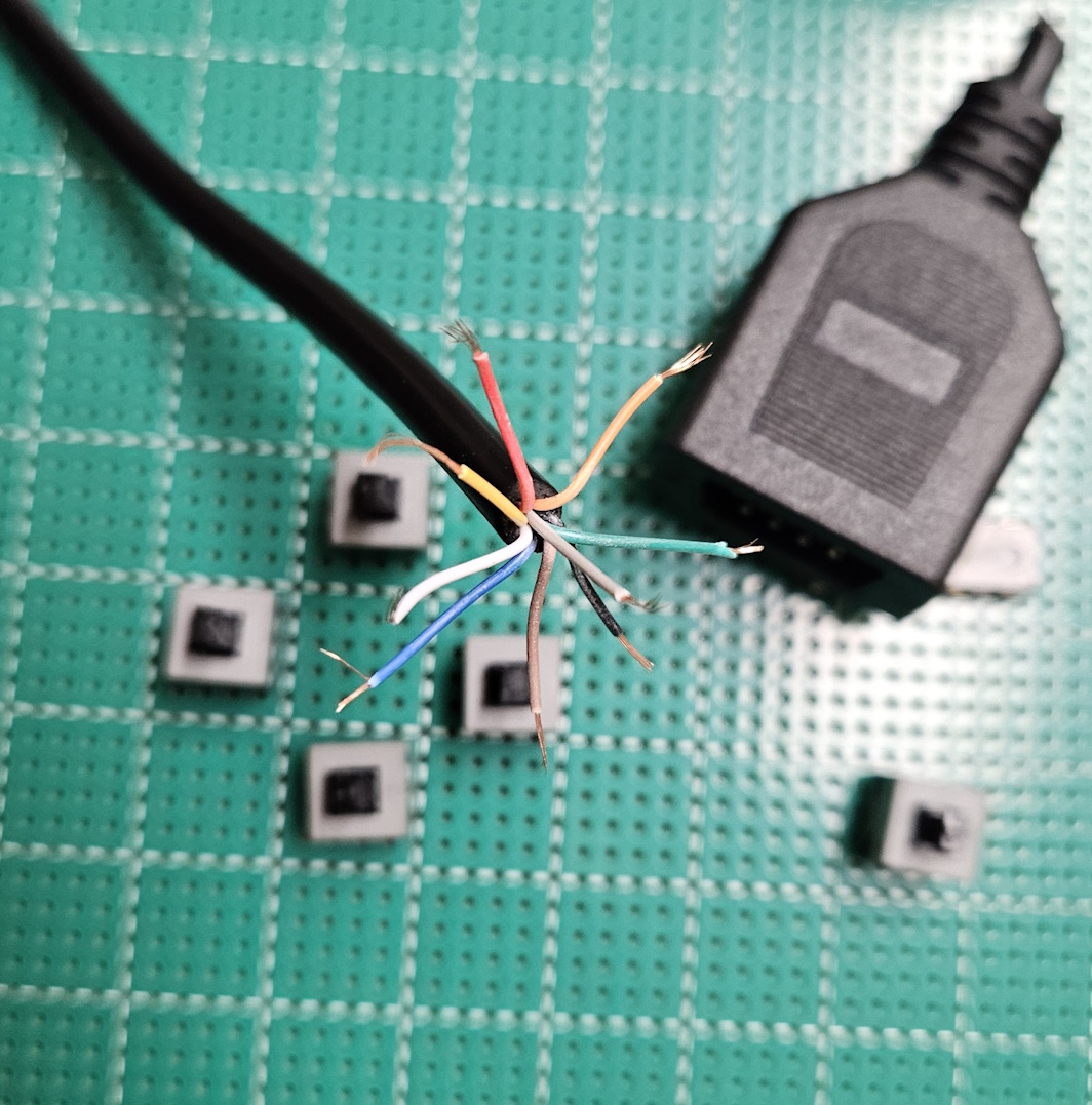
As for the cable that connects my controller to the console, I cut the male end off of the cable, stripped the shroud off of the end (revealing the 9 skinnier cables within), stripped the inner wires, then screwed down the wires in their designated terminal. The reason that I used screw-terminals instead of just soldering the wires to the board was that it would be easier to correct any mistakes. I did have the pinouts wrong at first, so I was thankful that I just had to screw the wires into different terminals instead of desoldering and resoldering a bunch of wires. Although in hindsight it would have been a good idea to install a female db9 port on my controller so that I wouldn't have had to cut and strip the extension cable. It also would have made the cable easily reusable for other applications.
In order to relieve stress on the cable and prevent the wires from been yanked out of their terminals, I bent some ordinary staples around the cable, pressed them down tight-ish against the cable, then soldered the staples down on the other side of the board to hold them in place. It seems to work well.
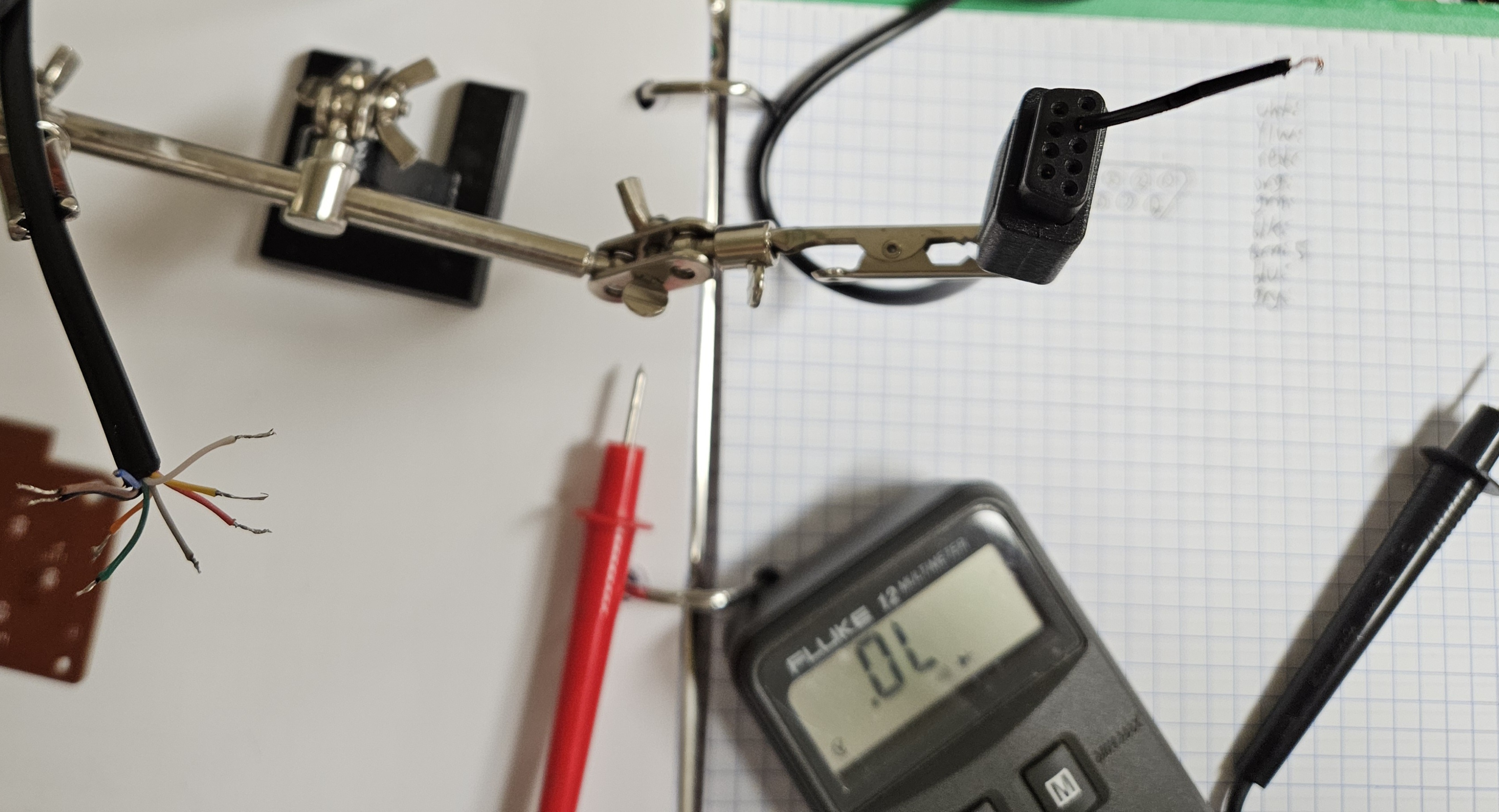
In order to determine the cable pinouts for the extension cable that I cut, I stuck a little piece of wire into each hole on the plug, then tested for continuity between that piece of wire and each wire in the wire bundle until my multimeter confirmed continuity with a beep. I then documented in my notes which pinout is associated with which wire color. As I mentioned earlier, you'll want to remove the 74157 chip from the OEM controller when you're probing it's cable pinouts.
You can also see that, instead of using very short wires to connect the resistors in what I like to call "resistor alley", I just soldered down some legs which I had cut off of the resistors in order to connect them all.
I constantly tested the continuity of my connections throughout this project with a multimeter when I could. This was in order to confirm that everything had proper, functioning connections. I did this because it would be easier to narrow down any issues if something were to go wrong.
In the end, it almost worked first try. The directional buttons and the A button worked, but every other button would reset the console (lol). I had to use a regular controller in order to get into the game and test the buttons. It was an easy fix, though. You see, when I inserted the resistors into the protoboard I had bent most of their legs inwards so that they would stay put when I soldered them. However, I forgot to cut these legs after I soldered them, so they were all touching each other. Stupid oversight, but luckilly it was an easy fix and it didn't seem to cause any damage to my spare Genesis.
Overall this has been a fun project and it's been a very educational process. While it was kinda tedious at times, it was worth it. It was pretty funny playing Sonic 2 with this abomination of a controller while testing it out. It will also serve as a basis for my arcade stick, as well as a stepping stone towards building an arcade cabinet.